
By Christie Jones, VP - director of marketing, SPIROL International Corporation
Designers can optimise the performance and total manufactured cost of a joint by understanding the differences between cold headed and machined solid pins. Both manufacturing methods produce high-quality, consistent parts. However, there are significant cost and capability differences between cold heading and machining.
Solid pins are common fasteners used for aligning, joining and assembling multiple components, mostly useful where the clamp load of a bolt is not needed. They are also used for specific functions, such as locating components, hinges, tamper resistant designs, etc. Two common manufacturing methods used to produce solid pins are cold heading and machining. Interestingly, many outside diameter ground dowels are not actually machined. It is common to pass cold headed blanks through a secondary grinding operation in order to produce the outer diameter ground dowels.
It is important to understand the differences between cold heading and machining when designing a solid pin for an assembly, as the manufacturing method directly impacts the design specifications, such as tolerances, geometry, and material, that can be assigned to the solid pin (Figure One). The objective of this paper is to educate designers about the differences between cold heading and machining, so they understand how to design a solid pin that optimises performance and reduces total manufactured cost of the assembly.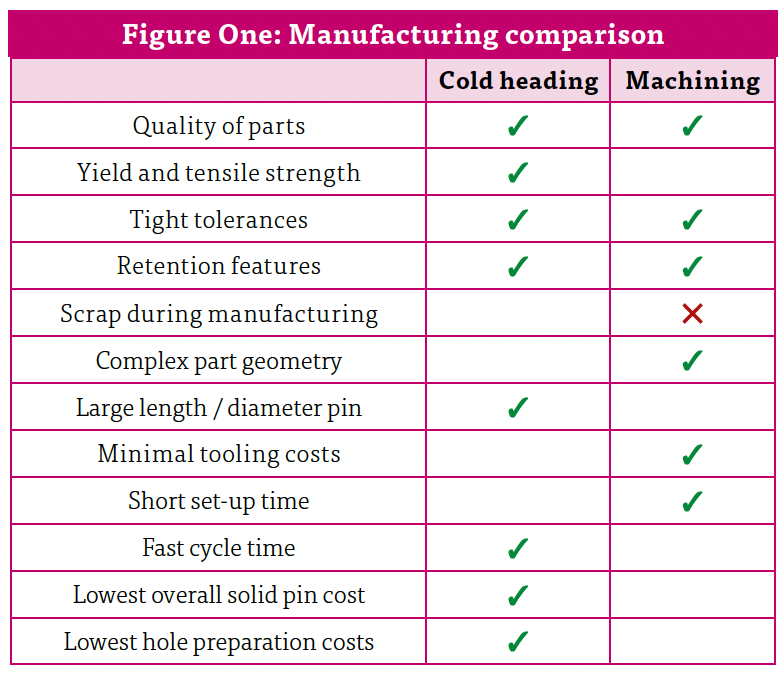
Machining is the process of cutting raw material (rod) into a desired geometry using cutting tools. This operation is typically performed on a lathe, with machining producing scrap in the form of chips.
Cold heading is the process of forming raw material into a desired geometry by upsetting the material (wire) in one or more dies. The most common method of cold heading fasteners uses one die and two blows, as this is sufficient for forming chamfers and heads. Dies provide cavities used to form the desired geometry, while a blow describes the physical process of upsetting material with a machine stroke. Additional dies and blows are needed as geometry becomes more complex. There are also limitations to the amount of material that can be displaced per blow.
Cold heading sometimes includes a wire drawing process that hardens the material, increasing both the yield and tensile strength. Machined pins produced with the same base material will have lower yield and tensile values because the material grain structure has been interrupted.
The first step in designing a joint is to establish the functional requirements of both host components and fasteners. Performance requirements should be achieved without over specifying the design. An ideal joint satisfies performance and quality requirements at the lowest possible cost. 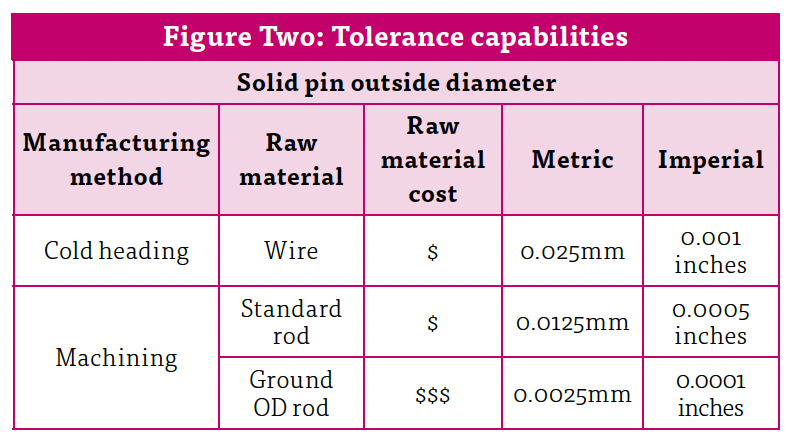
Press fit dowels and straight pins are typically retained in the assembly by being pressed into holes that are smaller than the pin diameter. In most applications, interference must be limited to keep insertion forces within practical limits. The acceptable press fit for most metals (steel, brass, and aluminium) is 0.0125mm – 0.025mm of material displacement. Since this tolerance threshold includes the sum of the tolerances of both the pin and hole diameter, pins must be precision machined and holes must be reamed and/or honed. This increases cycle time and manufacturing costs associated with hole preparation. It’s also important to recognise that free fit hinges do not require press fit holes and should not require pin diameter tolerances tighter than 0.025mm (0.001 inches).
Typically, the outside diameter (OD) is the most critical solid pin dimension. Both cold heading and machining can achieve the tolerance specifications needed for the majority of solid pin applications (Figure Two). In fact, cold heading produces solid pins with OD total tolerances of 0.05mm (0.002 inches). Machining can achieve tighter OD tolerances than cold heading, but this generally requires special ground OD rod. This should be avoided if possible, as ground OD rod can be more than three times the cost of standard rod.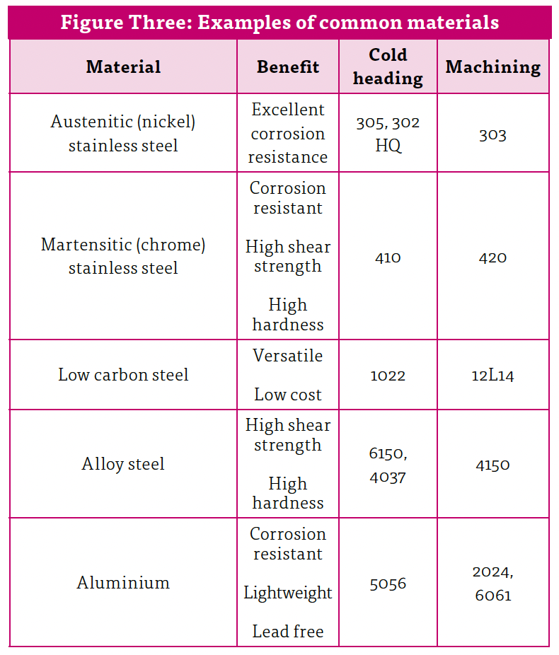
For solid pin length tolerances, machining and cold heading can achieve the same tolerance levels of approximately 0.25mm (0.010 inches) – this varies by pin length. The purpose of a chamfer is to allow for ease of assembly. A chamfer angle between 25° – 40° is suitable for the vast majority of solid pin applications and allows for maximum pin engagement. From a manufacturing standpoint, the optimal cutting angle (machining) is 45°, while the optimal forming angle (cold heading) is 30° or less.
The most common materials for solid pins are carbon and stainless steels. Raw materials are available in different forms depending on whether pins will be machined or cold headed. Commercially available material grades for rod and wire can differ. Rod is available in material grades best suited for machining, while wire is available in material grades suited for cold heading. Although material grades may differ, the important take away is that there are equivalent materials available for cold headed and machined solid pins. Hence, best engineering practices dictate that material specifications on drawings be relatively general if possible, such as carbon steel with hardness rating RC 27-33. Figure Three shows examples of several common materials for cold heading and machining for reference.
Cost comparison
Machined solid pins are typically about ten times the cost of cold headed solid pins (Graph One). Why are cold headed solid pins so much 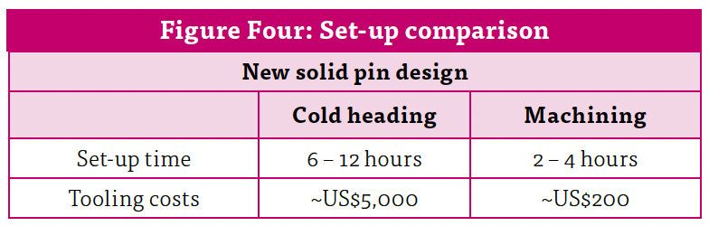 more cost effective? Cold heading produces solid pins at a rate of about 300 parts per minute (ppm), while machining yields approximately 4ppm. Machining also generates scrap, hence more raw material is needed to machine a solid pin than to cold head the same part. The only scrap generated during cold heading is that which is produced during set-up. Ground OD rod can cost more than three times as much as standard rod used for machining.
Although machining is more costly than cold heading, set-up costs are significantly lower for machining. Companies that standardise on solid pin sizes are able to mitigate set-up costs so there is a negligible cost impact to customers. However, set-up costs can be significant for custom designs, especially at low volumes. Figure Four outlines general differences between cold heading and machining set-up.
This paper can serve as a reference tool to assist designers with solid pin design specifications. However, it’s recommended that manufacturers partner with industry experts in joining and assembling to identify the lowest cost solution for their assembly. Machined solid pins are suitable for low volume custom parts, as well as highly critical alignment applications, when functional requirements dictate complex pin geometry. On the other hand, cold headed solid pins are suitable for the majority of applications – as most do not require machined tolerances. Cold headed solid pins are also suitable for free fit axles or hinge pins where the pins slip into place.
uk.spirol.com
![]()


Having spent a decade in the fastener industry experiencing every facet – from steel mills, fastener manufacturers, wholesalers, distributors, as well as machinery builders and plating + coating companies, Claire has developed an in-depth knowledge of all things fasteners.
Alongside visiting numerous companies, exhibitions and conferences around the world, Claire has also interviewed high profile figures – focusing on key topics impacting the sector and making sure readers stay up to date with the latest developments within the industry.
Don't have an account? Sign Up
Signing up to Fastener + Fixing Magazine enables you to manage your account details.

