
By Peter Standring, technical secretary, Industrial Metalforming Technologies
The terms heading and forging relating to the manufacture of fasteners seem such humble subjects and yet, what appears as obvious and self-evident – as something practised by ‘smiths’ for millennia – can also hold secrets that can easily be overlooked. It is these underlying aspects of heading and forging that this article seeks to address.
As everyone knows, forging changes the shape of a workpiece. Heading is simply one specific application of forging. But, what to forge? Nodules of gold – a malleable shiny pebble to early humans – or iron rich meteorites. Being found on the ground, these were probably the first materials to be worked by forging between two hard stone surfaces. Chemistry kicked in when fire produced metallic elements, which were discovered accidentally from smelted ore. It is from such serendipitous beginnings that the world we inhabit was built.
Industrialisation created a demand for ‘things’ and once a competitive process was developed, any number of the same ‘things’ could be produced. In the case of metals, flat strip/plate was rolled, as were lengths of material having the same cross section – round, square, ‘T’, ‘H’, ‘I’, etc. Such products were desirable and necessary for building ships, railways, electrical wiring and cables, etc. However, they required further processing to be made into the multi-functional metal components found in every aspect of commercial, business and public life.
The reason, because most single item metal objects have non-constant cross sections. Changing constant cross sections produced by primary processing (rolling) introduced a requirement for secondary and tertiary processing methods for example, forging using machines. Where, for centuries, ‘smiths’ used their own strength to achieve shape change, industrialisation gave rise to the machine that naturally increased the forces that could be applied.
Forging
Until the introduction of electronics, and the subsequent development of digitisation, all powerful human groupings relied for their weapons of war/defence on the ability to ‘forge’ metals. Swords and spears gave way to big guns and battleships. Throughout centuries, those having the skills and abilities (the metalworkers) to provide the people in power with the reason for their power, ensured that they always dined at the top table. Somewhat surprisingly, global political issues have shown that non-electronic weapons, and the means for their mass production, are still required today.
Three basic ‘machine’ forging methods are used: Open and closed die (both hot) and cold (which is almost always closed die).
Hot forging is carried out to reduce the forging force required. By raising the temperature of a workpiece (particularly a complex alloy) it is possible to change its crystal structure so that it is easier to deform. The forming force and workpiece deformation generates internal friction within the workpiece. In complex alloys, it is necessary to ensure that the heat transfer from the workpiece to the tools is balanced by the energy from the forging operation, which is entering the workpiece. Cooling or overheating of the work during forging can lead to defects. For some hot forgings, the cooling rate also determines the final grain structure of the workpiece and hence its properties.
Open die, as the term suggests, means the workpiece material can spread laterally relative to the forging direction. Closed die forging means forcing a workpiece into shaped die(s). In this situation, the volume of the workpiece must be sufficient to fill the die cavity. Too much material will place undue stress on the tooling. Where products having complex geometries are required, it is often necessary to use a multi-stage forging operation.
This is because unlike a casting process where the workpiece material is fluid and can flow into a mould, direct stresses on the die walls – produced with a solid workpiece – restrict material flow. This can be overcome using a series of intermediate blows or tooling stations, which in effect, incrementally rather than continuously change the workpiece shape.
Because the process is ‘hot’, the final ‘as forged’ shape will be larger than the functional accuracy needed for assembly. This is subsequently achieved by final machining.
Cold forging takes place ‘below’ the temperature at which the workpiece crystal structure changes. For this reason, the workpiece material is generally required to be available in its most ductile (soft) state. Materials that have ‘free machining’ properties should not be used for cold forging since these are designed to produce the characteristics of brittle fracture needed for creating small chips. Some ductile materials can be ‘warm’ forged, which also reduces the forging force but does not change the crystal structure.
In all metalforming operations, the workpiece strain produced by changing its shape will introduce strain hardening. In hot working operations, and at normal forming speeds, the effects of strain hardening are removed by the elevated temperature. Too high a forming speed and temperature can produce cracking at shear boundaries inside the material – a defect known as ‘hot shortness’.
In cold/warm working, the effect of strain hardening increases the properties (strength) of the formed (as forged) material. The degree to which a workpiece can be formed is determined by the difference between the strain at which the material yields and that at which it fails. The stress/strain behaviour of common window or bottle glass at failure would show little evidence of permanent strain (ductility). This behaviour would be similar to a grey cast iron – and for that matter an elastic band! Whereas, a nylon rod subjected to a large tensile strain would go on and on extending without catastrophic failure.
So, whilst the material a workpiece is made from must naturally fulfil its specified design criteria, its selection, depending on the manufacturing process used to make a component, is of equal importance. Machinability is enhanced using ‘free cutting materials’ (small chips make for easier swarf removal) but it cannot improve the material properties. The yield (percentage of material in the final product relative to that used in its manufacture) is basically a measure of waste – on aerospace parts, and due to large-scale machining, the yield can be as low as 5%.
Hot forging naturally requires energy to heat a workpiece to affect the necessary microstructural transition prior to it being worked. Although it is not possible to improve the material properties through strain hardening, it is possible to obtain a modification in the structure through preferential material flow and controlled cooling. The high temperature can have an effect on the material ‘yield’ depending
on the atmosphere control and accuracy of the process.
Cold forging – as in fastener production – can produce very high ‘yields’ of the material employed. The forming processes can also improve the material properties through cold working (thread rolling provides a major benefit over machining).
As always, the variables involved in cost-effective manufacture are determined by the number of parts required. Small batches are conditional on available stock, equipment, set-up times, etc; as in direct costs. Indirect costs, although important, tend to be considered as overheads.
Medium size batches, whilst fewer in number, offer manufacturers an option of grouping families of products into those requiring similar manufacturing options. Having a more consistent throughput allows greater investment possibilities for the achievement of cost-effective production efficiencies.
Guaranteed large-scale production makes it possible to invest in dedicated facilities and with the correct set-up, the most cost-effective methods of mass production available.
Heading
Since most screw type fasteners have heads, this operation has been selected to illustrate some aspects of the foregoing. Heads can be virtually any shape – spherical, as in ball joints, or wedges – as well as have axial symmetry or off-set geometries. For the sake of simplicity, the example chosen here will be a conventional symmetric/concentric hexagonal form. This can be hot, open die forged between flat parallel dies and then trimmed in a die or by machining. The thickness and diameter of the head will be determined by the volume of the upstand of the workpiece (usually cut from rod) above the lower die. The aspect ratio of upstanding height relative to the workpiece diameter (H/D) is limited by the ‘buckling’ ratio. As the bulk of the workpiece is captured in one of the tools, this ratio can be increased if the opposing tool is shaped to prevent the work from sliding off its axis under compression. However, even if both ends of the upstanding workpiece are captured, the ‘slenderness’ ratio predicted by the Euler Critical Buckling Load will still pertain.
Assuming that’ buckling’ is not an issue, deformation of the upstand will take place by the centre core of the material being forced radially out from the axis. As the tools close, the captured part experiences no flow – whilst the outer surface of material above is caused to move outward and downward to be squeezed pancake fashion on the tool surface. At the free end where the material may not be captured, the frictional conditions existing between the work and tool will determine the shape of the deformation. Low friction will allow radial flow. ‘Stiction’ (total friction) will cause the material to behave in the same way as that at the captured end. Since all deformation occurs by shear, it is the movement of internal elements of material along shear boundaries that generates friction and shape change. Introduce boundaries – as in die walls – and the increase in external friction will naturally impact on the flow characteristics within the deforming material. It is for this reason that preforming (multi-stage tooling) is of such importance in obtaining a product that has complex geometry.
Hot closed die forging of a hexagonal head generally requires a two-stage operation. The first would be preforming the head of a circular rod in a conic tool. Shaped like a truncated wizard’s hat, this distributes the material to create the base pancake shape first. A second operation with the conic head inside a hexagonally shaped tool can then be used to complete the forming operation.
Cold forging is carried out in a similar manner but usually on smaller components produced from coiled wire. This is drawn, to ‘size’ the diameter, and then sheared to length. Depending on the type of machine used and the component being formed, the heading operation can be carried out in much the same manner as described above.
As in hot forging, given suitable workpiece material and equipment, the range and complexity of the component geometries that can be forged is determined by the skill and metal former’s imagination. This capability is significantly enhanced at the product design stage by the use of numerical simulation software. It should always be recognised that having design control provides significantly greater opportunities for cost savings in manufacture than is the case when a product is already defined. 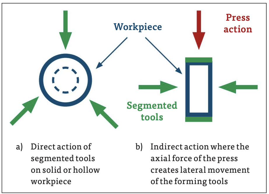
A first class example of the opportunities to be gained when ‘free thinking’, was presented in Stuttgart at the New Developments in Forging Technology by H. Gensert of SIEBER Forming Solutions in 2009 [1]. In his paper, Gensert proposed using three piece segmented tooling to laterally form solid or hollow fully finished components cold, on a conventional press as outlined in Figure One. His ideas involved using billets with preformed shapes to allow for the flow of excess material to ensure it did not interfere with the closure of the tooling segments. The shapes produced included conventional threads (without the misshaped crest often found on rolled threads); non continuous threads of virtually any shape – either with longitudinal and or radial discontinuities; also, constantly or variably changing geometries as in the polygonal shape of self-tapping screws. For those clever enough to identify the need for special products, techniques like these represent pure gold.
Conclusion
Today, the term ‘tech’ is assumed to be everything IT generated. It is worth noting that the future of future generations will be determined by how they manage the ‘finite’ resources of the planet and the technologies that use them. Goods made from a single source material offer ease of recycling but rarely display the properties required to be fully functional. Coating with diamond for enhanced cutting; gold for electrical conductivity or display; as well as plastic, paint or preservatives for protection; are all necessary but create problems with recycling. Where multi-functional materials are required for specific applications, these could be best applied (where possible) by use of easy to assemble and disassemble products. As always, such things are made possible by the use of fasteners and if adopted for the future – future fasteners.
All technology requires a ‘window of opportunity’ in order for it to succeed. Given the global driving force to combat the effects of climate change, the type of technology suggested in Gensert’s paper1, and others like it, could become a significant element in terms of forging a future.
References
[1] H. Gensert, SIEBER Forming Solutions, Formed Threads, International Conference on ‘New Developments in Forging Technology’, Stuttgart, Germany, May 2009, pp 135 – 141. (Edited M. Liewald, IFU, University of Stuttgart). ISBN 978-3-88355-375-7.


Biog
Will joined Fastener + Fixing Magazine in 2007 and over the last 15 years has experienced every facet of the fastener sector - interviewing key figures within the industry and visiting leading companies and exhibitions around the globe.
Will manages the content strategy across all platforms and is the guardian for the high editorial standards that the Magazine is renowned.


