

By Morten Schiff, chief executive officer, Vibrationmaster
Validating and optimising bolted joint design delivers safety and performance improvements, alongside streamlining costs. There is now a powerful new vibration test methodology using controlled shear force loading. It is significantly more advanced than traditional – and flawed – displacement amplitude-driven Junker testing. This new approach enables users to test bolted joints for resistance to rotational self-loosening under real-world conditions.
Testing is essential, but existing validating bolted joint integrity tests are flawed
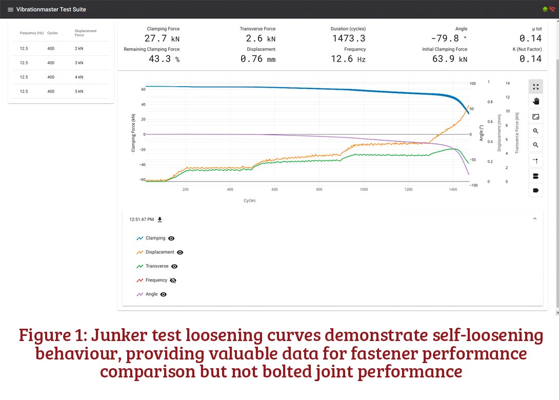
Fastener manufacturers, fastener distributors, and the design engineers within end-users, typically vibration test bolted joints to understand self-loosening behaviour and the performance of the locking elements intended to prevent rotational self-loosening. The results, traditionally generated by Junker testing, are extrapolated to underpin assumptions about how the resulting bolted joint will perform under operating conditions.
Although valuable, existing tests such as Junker’s are flawed when used in this way. Junker testing is a powerful tool when comparing various fastener locking elements, such as lock nuts, wedge washers and chemical locking, to prevent self-loosening. The DIN and ISO standards are useful for product comparisons. But the Junker tests required by these engineering standards result in forced full displacement on the bolted joint from the outset. This is not what happens in real-world situations and not what bolted joints are designed for.
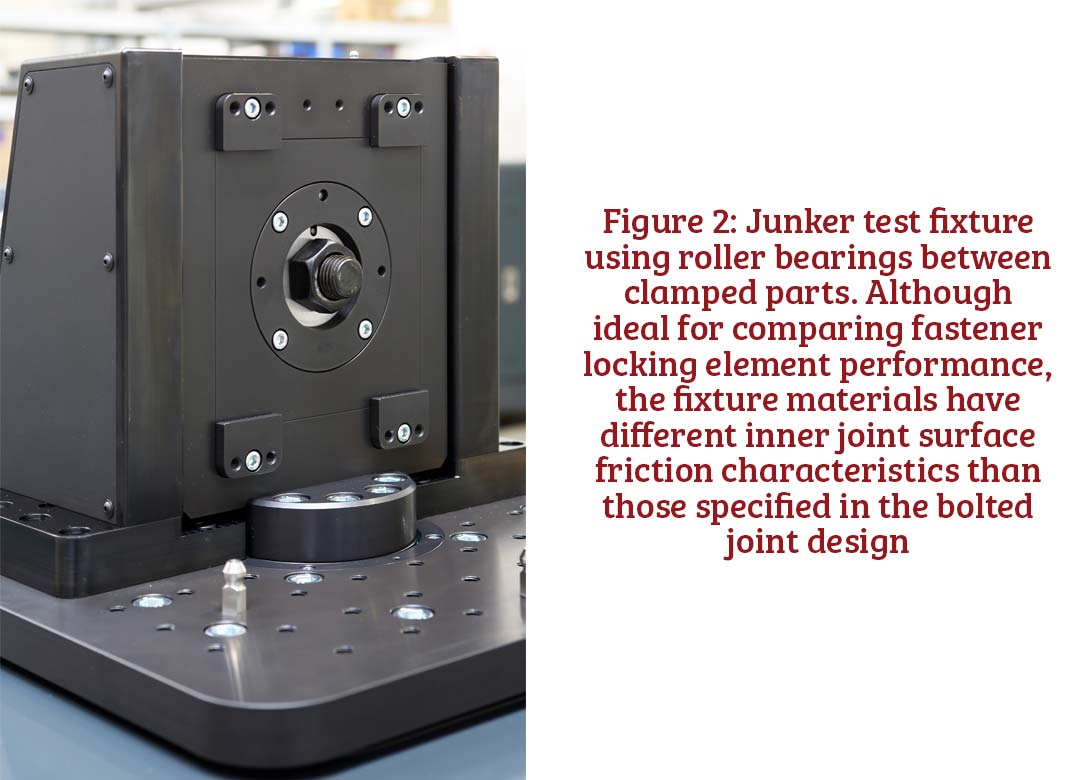
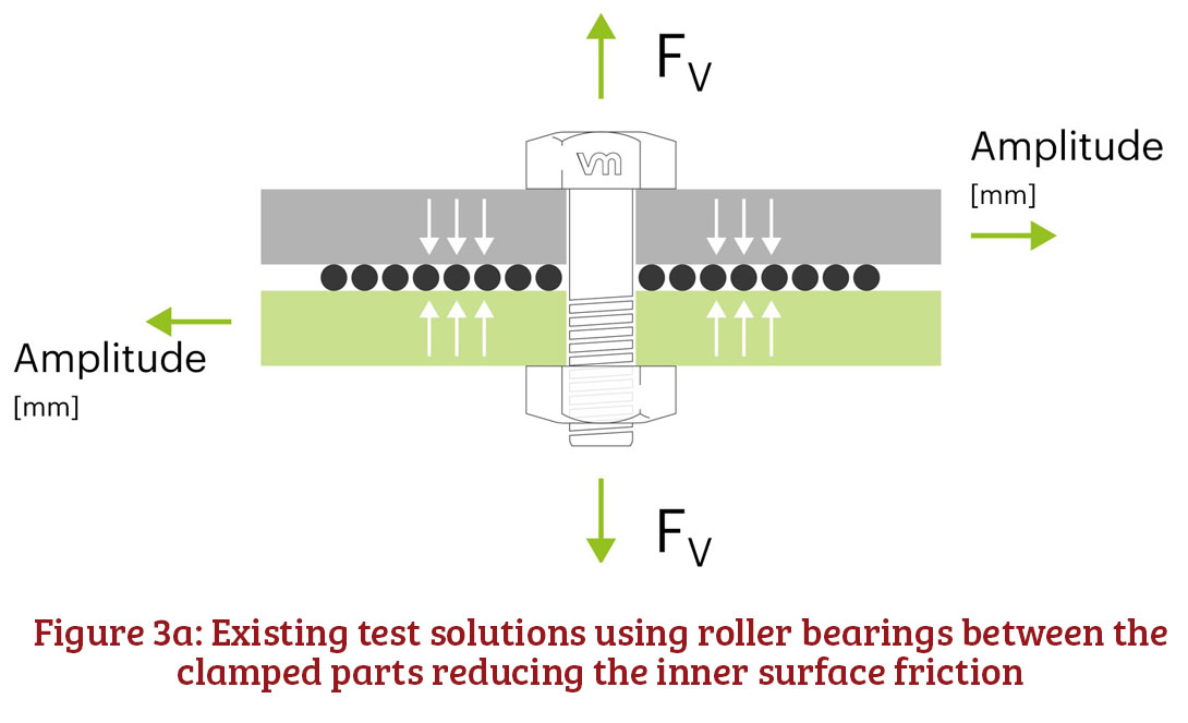
There is another challenge. Existing equipment solutions test fasteners using fixture plates with roller bearings in between that do not have the same inner joint surface friction as the materials that are specified in the bolted joint design. As a result, they have completely different performance characteristics, such as friction coefficients. Roller bearings in existing Junker test machines mean the actual surface friction between the clamped parts is much lower than that of the real bolted joint design. Both these factors, forced full displacement and the use of roller bearings to ease the amplitude driven movement between the clamp surfaces, mean the bolted joint is not undergoing testing in anything like real-world conditions.
Rotational loosening theories and resulting standards require updating
The theory underpinning the existing widely used vibration tests has also advanced. In 1969, what was then ground-breaking research by Professor Gerhard Junker1 showed that rotational self-loosening occurs when a transverse load is acting perpendicular to the bolt axis of a preloaded fastener connection. As a result, the conventional testing strategy for the last half-century has been to use Junker tests, and more recently measure the effectiveness of fastener locking elements against one of the three common standards: DIN 651512, DIN 252013 and ISO 161304.
These standards require forced full displacement on the bolted joint from the outset. In real-world operating conditions, when a bolted joint is subjected to a shear force, it has been specifically designed not to result in slippage between the clamped parts. The very reason for the existence of a bolted joint is to maintain integrity. In real-world conditions, the transverse shear force load may, when it reaches a high enough magnitude, trigger limited microslip initially.
Only when the shear force increases to the point when it triggers slippage between the clamped parts does the displacement amplitude increase. The result is relative motion in the threads and rotational self-loosening starts. The relative motion cancels the grip caused by friction and generates an off-torque, which is proportional to the thread pitch and to the clamping force. If the friction under the nut or bolt bearing surface is overcome by the off-torque, the off-torque then rotates the nut or bolt, so it loosens, leading eventually to bolted joint failure.
Introducing closed-loop controlled transverse shear force vibration testing
Advances in bolted joint performance theory, and test equipment design, deliver a powerful new solution to check bolted joint integrity that overcomes the inherent flaws in Junker tests and the equipment currently used to conduct them. There are two key challenges to overcome: The forced full displacement amplitude driven Junker tests demand and the use of fixture plates with roller bearings reducing inner joint surface friction.
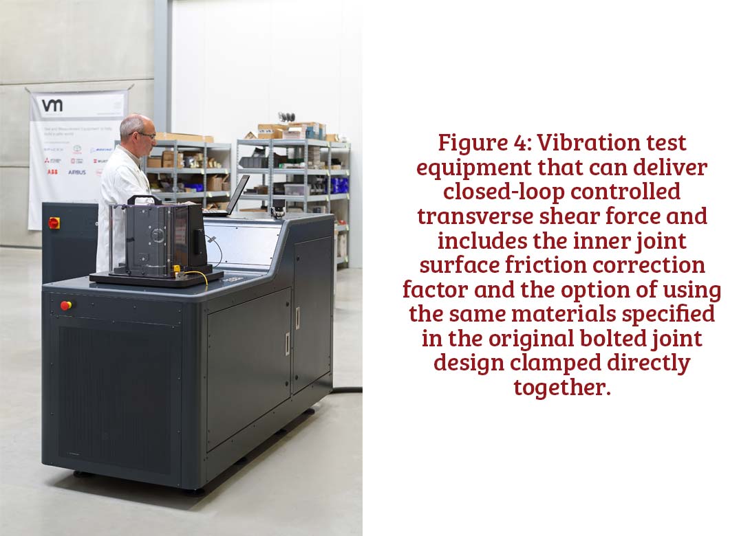
To overcome the first challenge, we do not create the test conditions that the DIN and ISO standards specify by applying full displacement amplitude from the outset. Instead, using innovative vibration testing technology, we apply a closed loop controlled transverse shear force to the bolted joint. If the joint has been designed correctly, this shear force will replicate the operating shear force and the joint will retain its integrity. However, when we increase the transverse shear force to the exact level where it triggers slippage between the clamped parts and increases the displacement amplitude, we know the shear force value at which the joint will fail.
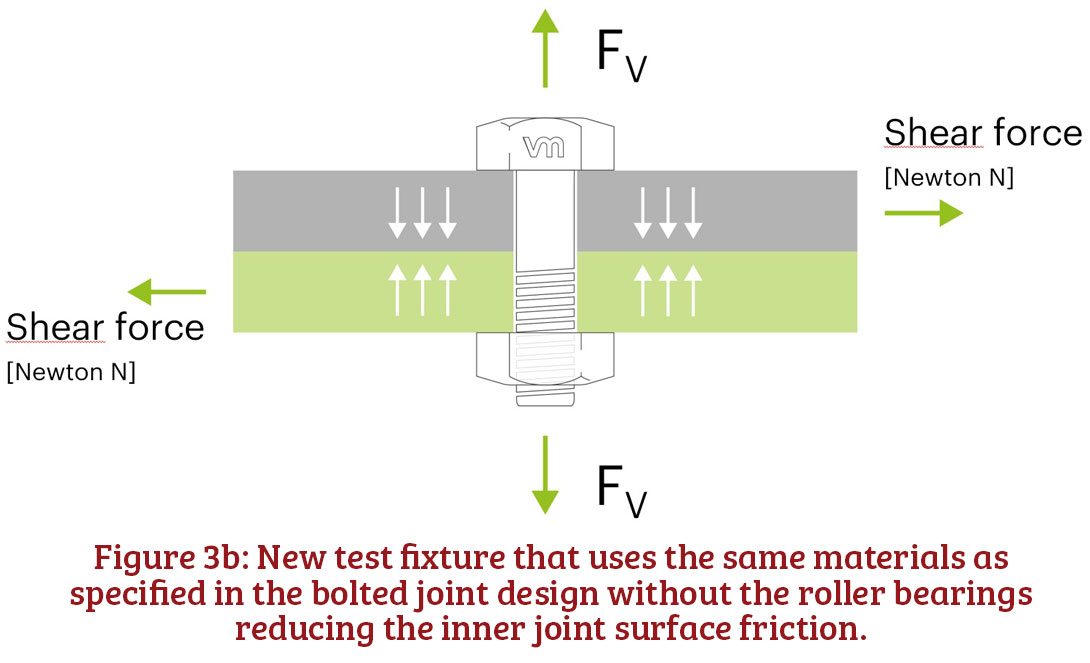
There are two solutions to address the second challenge created by using fixture plates with roller bearings that have incorrect surface friction performance criteria:
When using the new test methodology, the transverse shear force as measured in Newtons [N] is the lead parameter while the displacement amplitude measured in millimetres [mm] is simply a result of the forces acting on the joint. This is how a bolted joint behaves under operating conditions.
The outcome is a dataset and analysis of bolted joint performance under specific operating conditions that the fastener design engineer can apply to refine the bolted joint integrity.
Using test data to optimise safety factors and bolted joint design
Now we have a test that works. The closed loop transverse shear force test, incorporating the roller bearings and controlled shear force loading solution, can test real-life applications accurately and bolted joint performance under accurate simulated operating conditions.
The implications of this are significant – we can now determine a safety factor for the integrity of a bolted joint and, in turn, optimise the joint design.
If, for example, the operating transverse shear force on the bolted joint has been calculated by finite element analysis (FEA) to be 3,700N, we can test the joint using the correct materials or the roller bearing correction factor and deliver 3,700N. If there is no movement between the clamped parts, then the bolted joint has passed the test. Next, we can explore the bolted joint design’s safety factor. Let’s say we assume a safety factor of three and apply 11,100N. If the bolt continues to perform without the transverse shear force triggering slippage in the clamped parts, then we know we can either continue with a design that has a safety factor of three or, if the application does not require a safety factor of three, we can start optimising the joint design.
This new vibration test has two benefits. First, we can validate safety factors and establish whether the safety factor is proportionate for the application; and, second, we can optimise overdesigned bolted joint designs, leading to multiple additional benefits. There are many examples where machinery is subjected to extreme and out-of-scope stresses that require high safety factors. Construction plant and equipment is often used incorrectly, such as lifting loads that are too heavy or using a machine attachment for the wrong application. In this context, safety factors are much higher.
We know that many joints are over-designed, particularly in cars. They use bolt sizes and materials that are overrated for the specific application, resulting in unnecessary weight, size and cost. Perhaps we can use an M8 instead of an M10, or a different grade of material? If this bolted joint will feature in many units, this could result in a large cost saving. If many of these joints are used in the sub-assembly or product, this may mean a weight saving, which, in the case of a car design, could reduce emissions or could reduce space required because the joint has a smaller footprint.
Transforming bolted joint design through a new vibration testing approach
Previously, without building expensive and often unique one-time-use test rigs, engineers were unable to test how their bolted joint designs will perform under operating conditions, until the joints are prototyped or even in production. Also, testing for safety factors and joint optimisation had been a lengthy, complex and often expensive process.
Our unique vibration testing methodology and vibration test equipment enables all the stakeholders in the design of fasteners and bolted joints – from fastener manufacturers through fastener distributors to the design engineers within end-users – to benefit from greater certainty that their designs will perform as intended.
For further information about how our new closed-loop controlled transverse shear force vibration testing can assist with your fastener and bolted joint designs visit vibrationmaster.com
References
1. Junker G, New Criteria for Self-Loosening of Fasteners Under Vibration, Transactions of the Society of Automotive Engineers, Vol. 78, 1969, pp. 314-335, New York
2. DIN 65151: 2002-08 Dynamic testing of the locking characteristics of fasteners under transverse loading conditions (vibration test), Deutsches Institut für Normung c.V., Berlin 2002
3. DIN 25201-4: 2010-03 Annex B Test specification for demonstrating the resistance to self-loosening of secured bolted joints, Deutsches Institut für Normung c.V., Berlin 2010
4. ISO 16130:2015 Dynamic testing of the locking behaviour of bolted connections under transverse loading conditions (vibration test), International Organisation for Standardization, Geneva 2015


Will joined Fastener + Fixing Magazine in 2007 and over the last 15 years has experienced every facet of the fastener sector - interviewing key figures within the industry and visiting leading companies and exhibitions around the globe.
Will manages the content strategy across all platforms and is the guardian for the high editorial standards that the Magazine is renowned.
Don't have an account? Sign Up
Signing up to Fastener + Fixing Magazine enables you to manage your account details.

