By John Muir, technical manager, Construction Fixings Association
In the world of post installed anchors into concrete and masonry, all chemical and mechanical anchors need to be tightened against a fixture through application of a defined level of installation torque, with one exception.
Applying a specified level of torque to an anchor (called the installation torque – Tinst) is required to create a clamping force to the fixture to ensure no movement takes place under load. Additionally, in the case of torque controlled expansion anchors, the installation torque creates the expansion force in the anchor, which produces the frictional resistance to the axial applied load.
The clamping force produced will always be well in excess of any applied load to the anchor – ensuring no movement or loosening takes place. The value of torque to be applied is provided by the manufacturer in the product’s European Technical Assessment (ETA) and Declaration of Performance (DoP), and is obtained through testing and calculation to ensure the correct magnitude of clamping force is achieved.
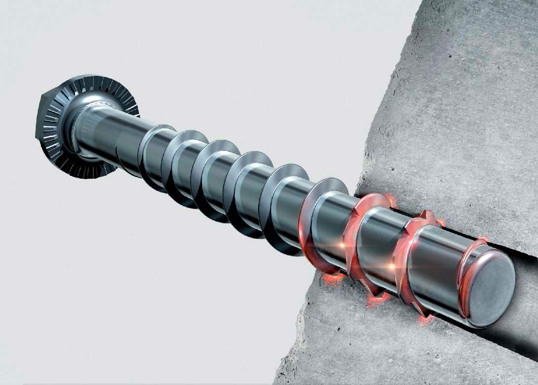
The one exception, as mentioned earlier, is the concrete screw anchor with a cutting thread, which when screwed into the base material cuts that thread form into the concrete or masonry.
The base material is drilled using a hole diameter that is less than the thread diameter of the anchor, so that the cutting thread of the concrete screw creates a physical key in the base material. The depth of the cutting thread affects the load capacity of the anchor – the higher the thread, the higher the load.
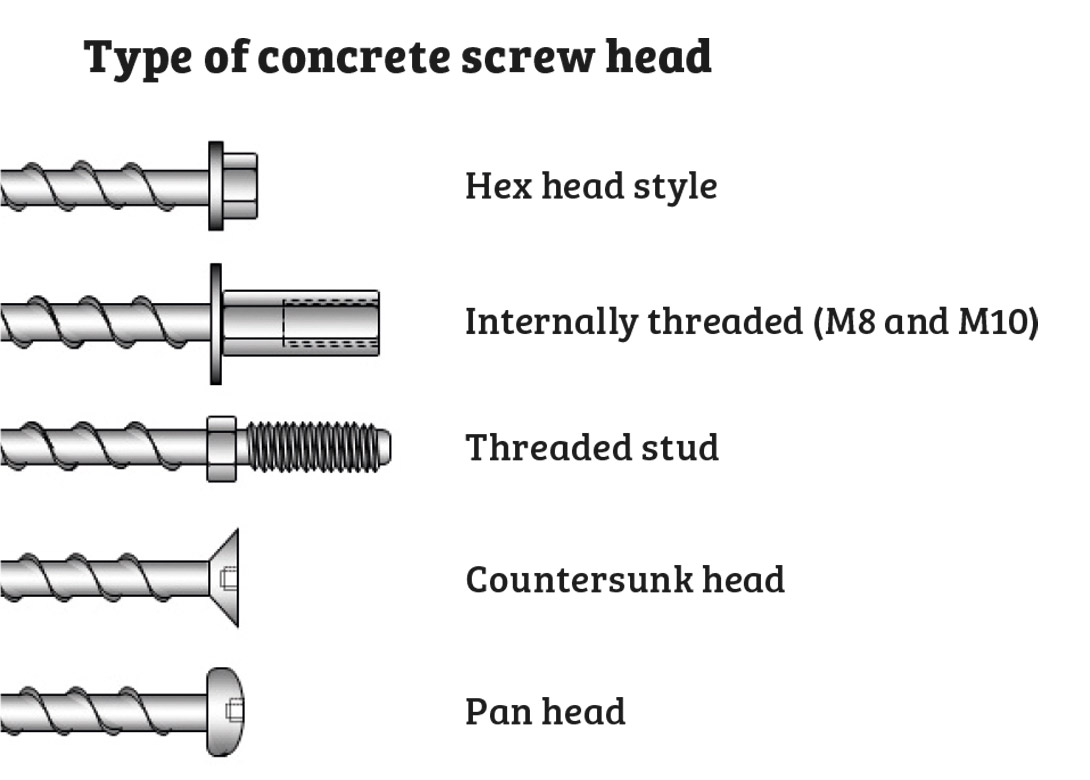
The varying head details make the concrete screw a very versatile product for a wide range of applications.

Since the working principal for concrete screws is keying, they are suitable for use in cracked concrete and in certain cases for dynamic loading such as seismic, fatigue and shock, making them very versatile.
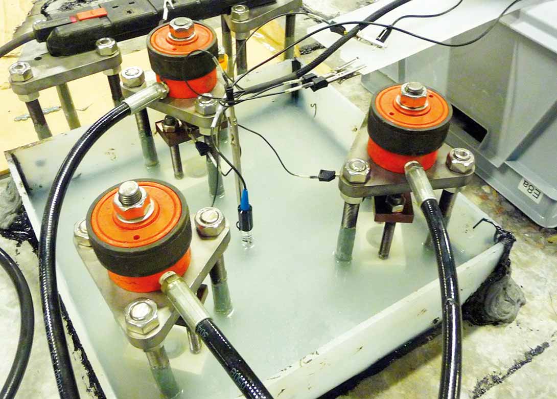
An issue that has arisen with certain concrete screws is that of hydrogen embrittlement. For these anchors to cut a thread into hard concrete, they are manufactured from a high strength grade of steel, which is more susceptible to hydrogen embrittlement. This can occur when a galvanised product is exposed to an electrolyte (e.g used in a damp or external environment) or when in production hydrogen is absorbed during the hardening heat treatment and coating process. A number of cases of failure of the anchors have occurred due to this effect in the past.
However, concrete screws can be manufactured so that de-embrittlement processes remove and limit the possibility of hydrogen within the structure of the fastener. The ETA testing for concrete screws, in accordance with the latest European Assessment Document – EAD 330232-00-0601, also now includes a specific test for resistance to hydrogen embrittlement, so a concrete screw with an ETA will have no issues in this area, which may not be the case with non-ETA products.
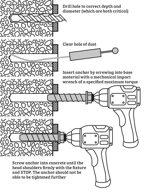
As mentioned earlier, the key difference with this product to other anchors is in the installation procedure, with the method of installing all concrete screws outlined below:

Concrete screws are referenced by the hole diameter, which is less than the cutting thread diameter, and clearance holes in a fixture are generally ~ 2mm greater than the thread of the anchor. This being the case, care needs to be taken to ensure any clearance hole is of an appropriate diameter to allow through drilling and fixing of the concrete screw. For instance, a 14mm clearance would be required for a 10mm concrete screw – 10mm hole diameter.
The suitable mechanical impact wrench for each manufacturer and anchor size will be defined in the ETA or DoP as the Timp.max. It is vital that any impact wrench used does not exceed this value of torque.
The key feature of this product is the fact that it is not set to a specific torque during installation. It is distance controlled not torque controlled.
There are, however, cases when a specific torque value is applied to the anchor. These include the situation where manual installation would be considered realistic or desirable, but only achievable in lower strength materials such as green concrete or masonry. Secondly, where the anchor is partially withdrawn and reinserted to allow for adjustment.
In these situations, the manufacturer of the concrete screws should be consulted. Installation torque (Tinst) for these examples will be much less than Timp.max and is published in the ETA and DoP.
Another example where Tinst is used is where a component, such as a plate or channel, is fixed to an installed anchor. This can only apply to a concrete screw with the protruding threaded stud, or internally threaded hex head. Here Tinst is applied to create the clamping force on the fixture, and is the maximum torque to be applied.

A typical example of the two cases above include:
Timp.max = 600Nm
Tinst = 60Nm for concrete and 5Nm – 15Nm for masonry
It is vital that there is no confusion over these values.
In summary, the concrete screw is a relatively new anchor, which has a good performance, covers a wide range of applications and is simple to install in a range of base materials.
However, since it utilises an installation method different to existing anchor types, it is vital that installers of these anchor have the knowledge of the installation method and, as with all anchors, have the expertise required to carry out the installation correctly.
The key points are:
Provided these key characteristics of this anchor are understood and adhered to, the construction industry will be able to utilise this flexible, innovative anchor to solve anchoring issues across all trades and applications.
Don't have an account? Sign Up
Signing up to Fastener + Fixing Magazine enables you to manage your account details.